Initial Board Setup
This section describes how to connect SiMa’s Evaulation/Developer Board to your host machine using the available ports.
Connecting to the Board via UART USB
To run a terminal emulator on your host machine, follow the steps below:
Install the appropriate terminal emulator on your machine. Each section below recommends a specific terminal emulator to illustrate how it works, but it is not necessary to use the programs specified in this section.
Configure the following parameters when launching the terminal emulator:
Baud rate: 115200
8 data bits
No parity
1 stop bit
Set hardware flow control to No/OFF.
On Linux
On a Linux machine, we will use minicom as the terminal emulator which has been tested and is known to work well.
Steps
Install minicom using the following command:
sima-user@sima-user-machine:~$ sudo apt-get install minicom
Detect the appropriate serial device:
Turn on the Evaluation/Developer Board and ensure the board’s serial port #2 is not connected to the host machine.
Before connecting the serial cable between the host and the Evaluation/Developer Board, list out the serial USB devices on your host with the following command:
sima-user@sima-user-machine:~$ ls /dev/ttyUSB*
    ls: cannot access '/dev/ttyUSB*': No such file or directory
You may get a list of existing devices or the message above if none exist.
Now connect the board’s serial port #2 to the host machine using the micro USB cable provided and once again, list the USB serial connections.
With Development Kit 1, you will see:
sima-user@sima-user-machine:~$ ls /dev/ttyUSB*
    /dev/ttyUSB0 /dev/ttyUSB1 /dev/ttyUSB2 /dev/ttyUSB3
With Development Kit 2, you will see:
sima-user@sima-user-machine:~$ ls /dev/ttyUSB*
    /dev/ttyUSB0
Connect to the appropriate serial device number.
With Development Kit 1, configure your terminal emulator to connect to the third device from the lowest number,
/dev/ttyUSB2in this case. If there are other devices connected, then you should try to connect to the 3rd new device that appears after you connect the Evaluation Board serial port 2. For example, if before connecting the board,ls /dev/ttyUSB*already listed a single device,/dev/ttyUSB0, then the appropriate serial port will be/dev/ttyUSB3after connecting the Evaluation Board, not/dev/ttyUSB2. This is because/dev/ttyUSB3is offset 3 from/dev/ttyUSB1after connecting the Evaluation Board to the host.With Developent Kit 2, configure your terminal emulator to connect to the first device from the lowest number,
/dev/ttyUSB0in this case. If there are other devices connected, then you should try to connect to the 1st new device that appears after you connect the Developer Board serial port 2. For example, if before connecting the board,ls /dev/ttyUSB*already listed a single device,/dev/ttyUSB0, then the right serial port will be/dev/ttyUSB1after connecting the Developer Board, not/dev/ttyUSB0. This is because/dev/ttyUSB1is offset 1 from/dev/ttyUSB0after connecting the Developer Board to the host.
Run the serial communication program on your host machine. It opens the Evaluation/Developer Board.
Configure the serial port associated with the
ttyUSBvalue found above as a serial port using the configurations listed at the beginning of this section.sima-user@sima-user-machine:~$ sudo minicom -D /dev/ttyUSB2 -b 115200, 8n1 -w
In minicom, to set the hardware flow control to
OFF, follow the steps below:Press
CTRL+Aand then pressZ.Select
Configure minicom.Select Serial port setup.
Select
Hardware Flow Control, the Flow Control will change fromONtoOFF.
On Windows OS
On a Windows machine, we will use Tera Term as the terminal emulator which has been tested and is known to work well.
Steps
Detect the appropriate serial device by using the steps below.
Open the Device Manager by pressing the
Windows key + X.Select Device Manager from the menu that appears.
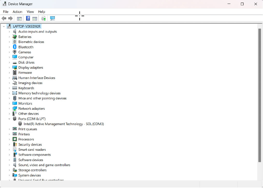
In the Device Manager window, expand the
Ports (COM & LPT)category. This category lists all the available serial ports on your system.Take note of the existing serial ports listed.
Connect the MLSoC serial port 2 to the host machine.
After Windows enumerates the board’s USB serial console port, four additional USB Serial Port COM ports should appear in the Device Manager.
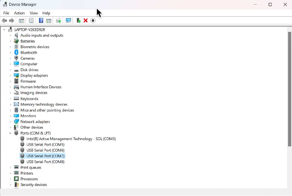
The newly added COM ports will appear as
USB Serial Port (com<n>)where<n>is an integer.The newly added serial port will typically have a name like
COMXorCOMXX, whereXis a number.For devkit 1, make note of the third device from the lowest number of new devices that appeared. For instance if
COM3,COM4,COM5andCOM6appeared then make note ofCOM5.For devkit 2, make note of the first device that appeared. For instance if
COM3appeared then make note ofCOM3.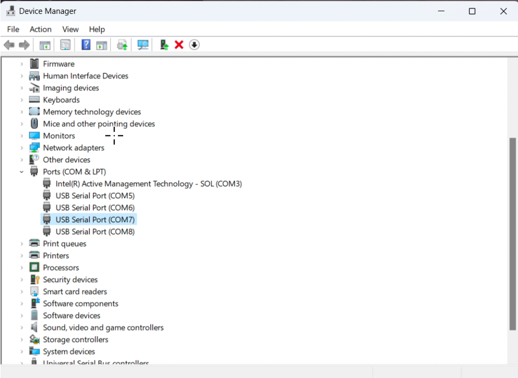
Open Tera Term and choose
serialfrom theNew connectionwindow, then choose theCOMport noted in the above step from the drop-down box.From the
Setupmenu of the Tera Term console, selectSerial port...and configure the serial port connection to the development kit’s console as shown in the figure below.Once configured, click
New setting. You should be connected to the development kit console. Press Enter to see the login prompt.
On macOS
On a macOS machine we will use minicom as the terminal emulator which has been tested and is known to work well.
Note
We support a Mac with x86 architecture. The M1/M2-based Mac is not supported.
Steps
Install minicom by using the following command:
sima-user@sima-user-machine:~$ brew install minicom
Detect the appropriate serial device by using the steps shown below:
Turn on the board and ensure the board’s serial port #2 is not connected to the host machine.
Before connecting the serial cable between the host and the board, list out the serial USB devices on your host with the following command:
sima-user@sima-user-machine:~$ ls /dev/cu.usbserial*
    no matches found: /dev/cu.usbserial*
A list of devices will be displayed, if they exist, or the message above, if they do not exist.
Now connect the board’s serial port #2 to the host machine using the micro USB cable provided and list the USB serial connections again:
With Development Kit 1 you will see:
sima-user@sima-user-machine:~$ ls /dev/cu.usbserial*
    /dev/cu.usbserial-142300    /dev/cu.usbserial-142301    /dev/cu.usbserial-142302    /dev/cu.usbserial-142303
With Development Kit 2 you will see:
sima-user@sima-user-machine:~$ ls /dev/ttyUSB*
    /dev/cu.usbserial-142300
Connect to the appropriate serial device number.
For Development Kit 1, configure your terminal emulator to connect to the third device from the lowest number:
/dev/tty.usbserial-142302in this case. If there are other devices connected, then you should try to connect to the 3rd new device that appears after you connect the board serial port 2. For example, if before connecting the board,ls /dev/tty.usb*already listed a single device,/dev/tty.usbserial-142300, then the right serial port will be/dev/tty.usbserial-142303after connecting the board, not/dev/tty.usbserial-142302. This is because/dev/tty.usbserial-142303is offset 3 from/dev/tty.usbserial-142301after connecting the board to the host.For Development Kit 2, configure your terminal emulator to connect to the first device from the lowest number:
/dev/tty.usbserial-142300in this case. If there are other devices connected, then you should try to connect to the 1st new device that appears after you connect the board’s serial port #2. For example, if before connecting the board,ls /dev/tty.usb*already listed a single device,/dev/tty.usbserial-142300, then the right serial port will be/dev/tty.usbserial-142301after connecting the board, not/dev/tty.usbserial-142300. This is because/dev/tty.usbserial-142301is offset 1 from/dev/tty.usbserial-142300after connecting the board to the host.
Run the serial communication program on your host machine. It opens up a new terminal on the board.
Configure the serial port associated with the ttyUSB value found above as a serial port using the configurations listed at the beginning of this section:
sima-user@sima-user-machine:~$ minicom -D /dev/cu.usbserial-142302 -b 115200,8n1 -w
In minicom, to set the hardware flow control to
OFF, follow the steps below:Press
CTRL+Aand then pressZ.Select
Configure minicom.Select Serial port setup.
Select
Hardware Flow Control, the Flow Control will change fromONtoOFF.
Connecting to the Board on the Network via SSH
Once we have the USB connection we can also set up your SSH connection, this should be our default connection method. This section describes the network connection methods.
Steps
To connect your board directly to your host machine, connect it over Ethernet. Our recommended way of connecting the board is to share your internet connection with the board so you can use the full power of Python using external packages.
To share your internet connection with the board, follow the instructions below for a Linux host system. Modify them appropriately for the Windows and macOS host systems.
On your upper right corner open
Settingsthen go to theNetworksection.Under the
Wiredsection, click the plus sign to create a new settings profile if you don’t have an existing profile for the board or just modify the existing one if you do.If you are creating a new profile, name the profile “Shared” or whatever you want.
In the
IPv4tab, chooseShared to other computers. Click Apply.If you had an existing connection, turn off and on the connection for the changes to take effect.
Your computer should now be networked with the AP.
10.42.0.0/24this is the default subnet used by Ubuntu for this setup, but there’s not necessarily a guarantee that your computer will use that subnet.If the next step returns no results, run
ifconfigand look for the IP of your Ethernet interface (usuallyeth0) there.
Open a terminal. Type the following to scan the devices in that IP range:
sima-user@sima-user-machine:~$ nmap -sn 10.42.0.0/24 | grep report
    Nmap scan report for sima-user-machine (10.42.0.1)
    Nmap scan report for 10.42.0.241
Here you will be listing the IP addresses used in this subnet. The one ending in
.1is your host machine. The one that doesn’t end in.1will be your board. From the code example above, the board is10.42.0.241and the host is10.42.0.1.Test the connection by running:
sima-user@sima-user-machine:~$ ssh sima@10.42.0.241
    The authenticity of host '10.42.0.241 (10.42.0.241)' can't be established.
    ED25519 key fingerprint is SHA256:wTptaqbB9zdLlKpWzRKnkb31cZKnvfmZ4ftXgwXU9kw.
    Are you sure you want to continue connecting (yes/no/[fingerprint])? yes
    Warning: Permanently added '10.42.0.241' (ED25519) to the list of known hosts.
    sima@10.42.0.241's password:
    Last login: Mon Nov 27 19:58:33 2023
davinci:~$
To test that you can connect to your host from the board, ping
10.42.0.1from the board, if you have an ssh server running in your host, you can also ssh:davinci:~$ ping 10.42.0.1 PING 10.42.0.1 (10.42.0.1): 56 data bytes 64 bytes from 10.42.0.1: seq=0 ttl=64 time=0.598 ms 64 bytes from 10.42.0.1: seq=1 ttl=64 time=0.703 ms 64 bytes from 10.42.0.1: seq=2 ttl=64 time=0.639 ms ^C --- 10.42.0.1 ping statistics --- 3 packets transmitted, 3 packets received, 0% packet loss round-trip min/avg/max = 0.598/0.646/0.703 ms davinci:~$ ssh sima-user@10.42.0.1 The authenticity of host '10.42.0.1 (10.42.0.1)' can't be established. ED25519 key fingerprint is SHA256:ic7JwZC8CdidIP3UaNBmAZ868j5HMm0oBBSc6IOgBNE. This key is not known by any other names Are you sure you want to continue connecting (yes/no/[fingerprint])? yes Warning: Permanently added '10.42.0.1' (ED25519) to the list of known hosts. sima-user@10.42.0.1's password: Welcome to Ubuntu 22.04.3 LTS (GNU/Linux 6.6.1-060601-generic x86_64) * Documentation: https://help.ubuntu.com * Management: https://landscape.canonical.com * Support: https://ubuntu.com/advantage Expanded Security Maintenance for Applications is not enabled. 81 updates can be applied immediately. 8 of these updates are standard security updates. To see these additional updates run: apt list --upgradable 37 additional security updates can be applied with ESM Apps. Learn more about enabling ESM Apps service at https://ubuntu.com/esm Last login: Mon Dec 4 18:29:29 2023 sima-user@sima-user-machine:~$
Additionally, verify that you can ping and SSH to your board from the Palette Docker container.
If you are unable to ping or SSH to the board, use the offline connection method as described below.
Connecting to the Board Offline
You can also connect to the board without an internet connection. The following instructions assume a Linux host system. Modify them appropriately for the Windows and macOS Host systems.
Steps
On your right upper corner open
Settingsthen go to theNetworksection.Under the
Wiredsection, click the plus sign to create a new settings profile if you don’t have an existing profile for the board or just modify the existing one if you do.If you are creating a new profile, select a profile name of your choice. For example, “Local”.
In the
IPv4tab, chooseManualand enter the following: * Address192.168.1.10* Netmask255.255.255.0* LeaveGatewayemptyWe recommend you to set up DNS as
8.8.8.8, 8.8.4.4.Click Apply.
If you had an existing connection, turn the connection ON and OFF for the changes to take effect.
Log in to your board using the serial device and run
sudo ifconfig eth0 192.168.1.20 up.Test the connection by running the following command:
sima-user@sima-user-machine:~$ ssh sima@192.168.1.20
    The authenticity of host '192.168.1.20 (192.168.1.20)' can't be established.
    ED25519 key fingerprint is SHA256:wTptaqbB9zdLlKpWzRKnkb31cZKnvfmZ4ftXgwXU9kw.
    Are you sure you want to continue connecting (yes/no/[fingerprint])? yes
    Warning: Permanently added '192.168.1.20' (ED25519) to the list of known hosts.
    sima@192.168.1.20's password:
    Last login: Mon Nov 27 19:58:33 2023
davinci:~$
To verify that you can connect to your host machine from the board, ping the ip address
192.168.1.10; or SSH to the host machine if an SSH server is running on your host machine:davinci:~$ ping 192.168.1.10 PING 192.168.1.10 (192.168.1.10): 56 data bytes 64 bytes from 192.168.1.10: seq=0 ttl=64 time=0.598 ms 64 bytes from 192.168.1.10: seq=1 ttl=64 time=0.703 ms 64 bytes from 192.168.1.10: seq=2 ttl=64 time=0.639 ms ^C --- 192.168.1.10 ping statistics --- 3 packets transmitted, 3 packets received, 0% packet loss round-trip min/avg/max = 0.598/0.646/0.703 ms davinci:~$ ssh sima-user@192.168.1.10 The authenticity of host '192.168.1.10 (192.168.1.10)' can't be established. ED25519 key fingerprint is SHA256:ic7JwZC8CdidIP3UaNBmAZ868j5HMm0oBBSc6IOgBNE. This key is not known by any other names Are you sure you want to continue connecting (yes/no/[fingerprint])? yes Warning: Permanently added '192.168.1.10' (ED25519) to the list of known hosts. sima-user@192.168.1.10's password: Welcome to Ubuntu 22.04.3 LTS (GNU/Linux 6.6.1-060601-generic x86_64) * Documentation: https://help.ubuntu.com * Management: https://landscape.canonical.com * Support: https://ubuntu.com/advantage Expanded Security Maintenance for Applications is not enabled. 81 updates can be applied immediately. 8 of these updates are standard security updates. To see these additional updates run: apt list --upgradable 37 additional security updates can be applied with ESM Apps. Learn more about enabling ESM Apps service at https://ubuntu.com/esm Last login: Mon Dec 4 18:29:29 2023 sima-user@sima-user-machine:~$
Note
For this second method, every time the board boots you must reset the IP address on the board. If you wish to avoid this, stop the board from booting using the Serial Device connection when this message is displayed:
U-Boot 2023.01 (Oct 09 2023 - 23:10:45 +0000)
Model: SiMa.ai DaVinci Combo Board
Board: SiMa.ai DVT board (933Mhz)
U-boot device tree name: simaai-davinci-combo-board.dtb
Linux device tree name: davinci-combo-board.dtb
DRAM:
DDR INIT: Target DDR controller frequency: 933MHz
DDR INIT: DDR initialization successful for all controllers
DDR INITIALIZATION SUMMARY
DDR 0: PASSED
DDR 1: PASSED
DDR 2: PASSED
DDR 3: PASSED
2 GiB
Core:  28 devices, 11 uclasses, devicetree: fit
WDT:   Started watchdog@0x700000 with servicing every 1000ms (60s timeout)
MMC:   mmc@00716000: 0, mmc@00717000: 1
Loading Environment from FAT... OK
In:    uart@0070d000
Out:   uart@0070d000
Err:   uart@0070d000
ETHPHY INIT: Initialization successful for all controllers
ETHPHY INITIALIZATION SUMMARY
ETHPHY 0: PASSED
ETHPHY 1: PASSED
ETHPHY 2: PASSED
ETHPHY 3: PASSEDSign Up To Receive Code
Net:   eth0: ethernet@1000000 [PRIME], eth1: ethernet@1200000, eth2: ethernet@14
00000, eth3: ethernet@1600000
Hit any key to stop autoboot:  0
Configuring the Static IP Address
Before you enable the SSH communication, you must configure a static IP address on the host machine and on the board. The static IP address can be configured to be temporary or permanent.
Temporary Static IP Address
When you configure a static IP address to be temporary, it will reset every time the board reboots.
Steps
Configure an IP address on the board by running the following command.
davinci:~$ sudo ifconfig eth0; sudo ifconfig eth0 192.168.1.20 up
Next, configure the IP address on the host machine.
Netmask:
255.255.255.0IP address should be set to something different than what was set on the board.
(
192.168.1.20in this case):192.168.1.[1-19, 21-254]
Run the
pingcommand on the host machine to the IP address on the board; it should show the correct IP address. If you see the IP address, the board has been set up correctly.
Permanent Static IP Address
When you configure a static IP address to be permanent, the board will always boot up in static IP address mode.
Steps
Connect to the board via UART and serial terminal.
Reboot the board.
Press any key to enter U-Boot when prompted with the message,
Hit any key to stop autoboot.Enter the following commands to configure the board to boot up with the previously set IP address.
sima:~$ env set forcenetcfg static; saveenv
sima:~$ boot
The board will reboot and use 192.168.1.20 as IP address for port eth0 and 192.168.2.20 for port eth1.
To modify the board’s static IP address, first reboot the board and log in.
Edit the network file using the
vicommand.davinci:~$ sudo vi /etc/systemd/network/20-eth0-static.network
In the Network section, update the IP address as needed.
To reset the connectivity back to DHCP mode, reboot and enter U-Boot by pressing any key when prompted to
Hit any key to stop autoboot; then enter the commands below and boot up the board.sima:~$ env set forcenetcfg dhcp; saveenv sima:~$ boot
Once you have confirmed the IP address of the board, you can connect to it using SSH protocol. For example,
ssh sima@192.168.1.20.Log in with your new password you set (per our suggestion earlier in the document) or
edgeaiif you have not yet changed the password.
Setting Up the Board in PCIe Mode
This section describes how to bring up the MLSoC board by connecting it to the host system using the PCIe interface.
Pre-requisites
Host machine operating system - we support Ubuntu 22.04 LTS, Ubuntu 20.04, and 22.10
- Host machine UEFI settings - for the driver to work as expected, the below options need to be enabled/disabled in UEFI/BIOS settings.
On the Intel-based machines, enable SRIOV, IOMMU, VT-D.
On the AMD-based machines, disable AMD-V and enable IOMMU.
PCIe Host Driver Dependencies
For the host machine to communicate with the MLSoC boards, it is necessary to have the host driver module loaded.
The host driver build and install is done via the automated script sima_pcie_host_pkg.sh, included in MLSoC1.4_Firmware.tar in the Palette software.
Follow the steps in Downloading the SiMa.ai MLSoC Images until cd MLSoC1.4_Firmware, including this step. Then come back to this page.
Every SDK release is linked with a specific firmware build. First let’s install all the neccesary requirements. Install GStreamer by following the official docs. Then install:
sima-user@sima-user-machine:~/Downloads/MLSoC1.4_Firmware$ sudo apt-get install make cmake gcc g++ dkms doxygen libjson-c-dev libjsoncpp-dev build-essential linux-headers-generic
Inserting the PCIe Connectors into the PCIe Slot
Once you have verified/upgraded the firmware on the Development Kit v2.0 board to the desired build number, follow the steps below.
Steps
On the board, there are four dip switches next to the UART serial port pins.
Make sure switch #1 is in ON position.
Connect the board via Ethernet & serial connection via minicom/PuTTy.
Set the static IP address for the board in U-Boot mode.
Move the switch #1 back to OFF position.
Make sure that the switches are set to (OFF, ON, ON, ON); required for the evaluation/developer board to operate in PCIe mode.
Make sure the single switch near the standalone power connection on the board is ON.
Power off the host machine.
Open up the computer casing - identify the PCIe slots.
Insert the PCIe connectors on the board into the PCIe slot on the host machine’s motherboard.
Close the computer casing.
Power up the host machine.
The next step is to install the drivers in our machine.
sima-user@sima-user-machine:~/Downloads/MLSoC1.4_Firmware$ sudo ./sima_pcie_host_pkg.sh
Upon successful installation of the drivers, reboot the system as prompted. You now have the appropriate PCIe host drivers and GStreamer plugins. Repeat this process to install a new version of driver and/or GStreamer plugin.
For debugging purpose, if you do not need the driver to be automatically loaded when the host machine reboots, create (or edit if already exists)
/etc/modprobe.d/blacklist.confand add the line blacklistsima_mla_drv. Once done, runupdate-initramfsand reboot the host machine. After reboot the drivers can be loaded manually usinginsmodormodeprobe.
Verifying the Installation
To make sure the software installation was successful and everything is in order perform the following three checks.
Steps
First, verify installation on the GStreamer side using:
sima-user@sima-user-machine:~$ gst-inspect-1.0 pciehost
Next, run the following code to ensure a successful driver installation.
sima-user@sima-user-machine:~$ modinfo sima_mla_drv
    filename:       /lib/modules/6.5.0-28-generic/updates/dkms/sima_mla_drv.ko
    license:        GPL v2
    author:         SiMa.ai
    description:    SiMa.ai MLA PCI Endpoint host driver
    version:        1.4.0_master_B1230
    srcversion:     12D635446AD9CD6A45C7371
    alias:          pci:v00001F06d0000ABCDsv*sd*bc*sc*i*
    depends:
    retpoline:      Y
    name:           sima_mla_drv
    vermagic:       6.5.0-28-generic SMP preempt mod_unload modversions
    sig_id:         PKCS#7
    signer:         USER-SYSTEM_NAME Secure Boot Module Signature key
    sig_key:        10:22:...:09
    sig_hashalgo:   sha512
    signature:      93:6A:96:26:18:25:D2:1E:9F:BE:35:2F:5F:BF:50:82:5C:9D:9F:F9:
            ...
            6E:21:AE:39:A4:2A:52:DC:D6:A3:6E:51:53:8B:A4:CD

This means that the driver installation was successful.
Finally, run the code below to confirm that the device has been recognized successfully.
sima-user@sima-user-machine:~$ lspci -vd 1f06:abcd
    0000:01:00.0 Processing accelerators: Device 1f06:abcd (rev 01)
    Subsystem: Device 1f06:abcd
    Flags: bus master, fast devsel, latency 0, IRQ 156
    Memory at 84000000 (64-bit, non-prefetchable) [size=1M]
    Memory at 6003000000 (64-bit, prefetchable) [size=1M]
    Expansion ROM at <ignored> [disabled]
    Capabilities: <access denied>
    Kernel driver in use: sima_mla_drv
    Kernel modules: sima_mla_drv

This means the hardware has been recognized succesfully.
Once the above verification steps are complete, you will be able to perform the following tasks.
Steps
Install the Palette software on the host machine.
Start the Palette Docker container.
Connect to the board using the command,
mpk device connect -s 0.Compile and package an application using
mpk create.Deploy the
project.mpkusingmpk deploy -f project.mpk -s 0.Start the host side script to send the video and receive the frames.